Showing posts with label repair. Show all posts

Sunday, January 3, 2021

Cleaning a vintage CCM bicycle wheel


The Canada Cycle & Motor Company (CCM) has a fascinating history. For many middle-aged Canadians today, during their childhood CCM was a respected household name for hockey equipment, including ice skates, pads, and sticks. But the company's origins date to 1899, when CCM manufactured high quality bicycles in Toronto as part of its operations with the Russell Motor Car Company. The picture below is from CCM's 1918 catalogue.


CCM's bicycle products carried through to the company's demise in 1983, although by the end they had gained a reputation as a cheap department store bike that competed with increasing low-cost imports from other markets, such as Asia. 


Although the lustre of CCM bikes has long since waned, many years ago I considered myself fortunate to have found a rear wheel from a CCM bicycle in a now-defunct antique store in Carleton Place. It's been on my to-do list for years to clean up this wheel so I could give I could display it in my office. 

According to information from this interesting site (based in nearby Perth, Ontario), it appears my wheel could date to 1908-1918. The hub is a "Hercules" armless coaster brake, one of CCM's models manufactured under license from Musselman (patent number 106391). 


The oil port in the middle of the hub is inscribed with what appears to be "JOSLUCASL2", "No 1" and "BIRMM". (I'm guessing this is a part made by Lucas Industries in Birmingham, England, which was a major centre of bicycle and motorcycle manufacturing and home of BSA.) Apparently, CCM marketed oil specifically for their Hercules coaster brake hubs in the late 1920s. Their brake grease didn't appear until the 1930s and even then the company recommended the periodic addition of a few drops of oil to preserve performance. (As a footnote, there was debate among cyclists as early as the late 1890s as to whether grease or oil was better for hubs!)


Since it's not a "New Hercules" model, it's almost certainly the original 1908 model as shown in the patent and product sheets below. 


The wooden rim was painted black and appears to lack evidence of pin striping, which was added to later, fancier models. It also lacks a metal rim strip added to reinforce later wheels, although there are two small nails and some cloth remnants near the valve hole, which probably held a cotton rim strip. As with modern rims, the valve hole is opposite the rim seam, which in this case is a glued finger joint. The wood is fine-grained and appears to be hard maple or maybe birch.


The hub and spokes are nickel-plated, the nipples are brass. 


I disassembled and cleaned the bearings and coaster brake mechanism, and straightened and chased the threads on the axle. It now works smoothly when reassembled! I also removed surface rust from the spokes and applied a conservator's microcrystalline wax to all metal parts to retard further corrosion. Varsol and linseed oil were used to clean and protect the wooden rim, as I felt this was an authentic and appropriate treatment given the probable age of the wheel. Unfortunately, there's too much corrosion to risk tightening the fragile spokes, so it won't be possible to true up the wheel. However, it holds its shape well enough as-is. 

As a bicycle enthusiast, I'm thrilled to have this wheel on display as a reminder of Canadian cycling heritage. I wonder who, a hundred years from now, may admire some of the wheels I've built?

Wednesday, June 24, 2020

Tenere 700 tail tidy: B&B Off-Road Engineering

As with many Japanese bikes, the Tenere 700 comes with an OEM monstrosity of a number plate holder hanging far past the tail light and adorned with chinzy reflectors, where it's readily exposed to breakage on your first tip-over in the woods. As with my WR250R, one of the first mods to my Tenere has been to show that booty some love and install a tail tidy. 

Now that the Tenere 700 has been out for a year, those of us in North America who are now just getting the bike can benefit from a wide range of tail tidy options. CamelADV, Adventure Spec, Rally Raid UK, and R&G all offer some good options. 

But the one I chose comes from B&B Off Road Engineering out of Australia, where there's a solid Tenere 700 following and some of the hardest-core riders of this bike in the world right now. I chose B&B's tail tidy because it offers a solid reinforced mechanical design, it doesn't require cutting the OEM plastics, and it has a good fit and finish and a decent sealed LED plate light. Mine was the first to be delivered to Canada, and having received it only 10 days after placing my order, I installed it right away in one evening. 

For Canadians considering the B&B option, I recommend ordering direct from Australia because factoring in the exchange rate and $30 of duties, it ends up significantly cheaper (and probably faster) than ordering from B&B's US distributor. plus I had excellent service from Sarah at B&B, who was quick to let me know when shipping to Canada was re-opened following the COVID shutdown. Go Commonwealth! 

All the parts come nicely bubble-wrapped. The included hardware is mostly metric stainless steel. I replaced some of the nuts with stainless locknuts (M5). 

What's in the box

The tidy is made from aluminum, doubled in places with welded reinforcements. The whole thing is coated in a thick optional black finish (standard is silver) that looks like it should withstand significant abuse.

Here you can see the reinforcement plate for the turn signal stalk. B&B has an optional insert to allow you to install round, threaded signal mounts, which I plan to adopt when I can order some LED signals. 


This is the top plate that bolts into your subframe. Again, beefy construction. 


The number plate light is a completely sealed LED unit. Looks to be decent quality for both the plastics and wiring.


I like how the metal wiring cover reinforces the structure of the number plate holder. There's no flex in this system, so I don't expect any metal fatigue cracking. 


B&B includes easy to follow instructions to remove the OEM tail assembly. The Tenere 700 is so easy to work on... all the bolts are easily accessible and all you need are 8mm and 10mm sockets and a 4mm and 5mm hex to remove the body panels. Make sure you label your turn signals so you know which side to install them on--the wiring only connects one way! 

Installation is a breeze. To connect the number plate light, I cut off the OEM connector and spliced it into the B&B wiring with some heat-shrink tubing and electrical tape to reseal the harness cover. Connect the white and black wires together (ground) and brown and blue together (+12V). Check your wiring by turning on the key before putting everything back together.

When installing the tail tidy wiring cover, I had a bit of a challenge threading in the 10mm cap screws provided in the kit because of some minor deformation of the aluminum and plastic coating on the aluminum threads. One bolt went in fine, but the metal on the other side of the cover was lifted up a bit and the short fastener wouldn't quite reach. I used a longer bolt to clean out the threads and wind things in with all fasteners installed loosely, then replaced the long bolt with the correct shorter one. It's really not that fussy though, and it all went together fine. Fit overall is excellent and no filing or drilling was required except to mount a reflector bracket (see below) and my number plate (no holes are provided). 


Here's all the crap left over. Easily a couple of pounds of plastic and metal! 


One thing the B&B kit is missing is a way to attach a rear reflector. I made a simple bracket out of some scrap stainless steel and sprayed it black with Krylon paint. Last thing I want is to get hassled (or worse)  during a police stop because I'm missing a required reflector! 


This is the OEM reflector bolted on. I drilled three holes in the B&B number plate holder to attach the bracket using some stainless steel bolts. 


There's nowhere to attach side orange reflectors, but what's neat is that even when you remove the OEM plastics, Yamaha has thoughtfully included knurled handgrips under the outer handgrips for the pillion passenger. The flat area right above the grips is a perfect spot to attach some 3M reflective tape. The tape is flush to the surface and therefore protected, yet provides a wide view of 10 square inches of reflector per side, versus the 3 square inches provided by the OEM round reflectors per side. A good conspicuity upgrade in my mind! 


One last note is that the brake light has a small bit of foam stuck to the bottom where it contacted the OEM plastics. When you've installed the B&B kit, this foam doesn't touch anything. I peeled it off and reattached it further inboard so it wedged between the light and the B&B plate. While it doesn't look like the tail light will move around much on rough terrain, repositioning the foam adds a little bit of extra vibration protection.

Overall I'm very pleased with this kit. It's easy to install (couple of hours), solidly built, and looks great. With the addition of a rear reflector and the side tape, I see no reason why the bike shouldn't meet the same regulatory requirements as the OEM configuration. 

Monday, February 17, 2020

ACF-50 corrosion protection for your bike and other toys


ACF-50 is an anti-corrosion spray originally developed and certified for use in aircraft, that also works great to protect your bike's metal and electrical parts. Think of it as a Krown treatment on steroids.

This is new product for me, something I only learned about from a UK rider who'd posted a comment deep in the ADVRider forums. Expecting sticker shock, I was pleased to find that a 1-litre jug with spray bottle could be ordered from Amazon for a mere $20.

Since I already had my WR250R apart to re-shim the valves, I figured I'd disassemble it further to do a deep-clean and ACF-50 treatment. After 10 years and 42,000km of trail riding, the WRR is in great shape thanks to regular inspections, cleanings, and preventive maintenance. Nevertheless dust accumulating in deep, hidden crevices can trap moisture leading to corrosion and electrical problems. It's not always feasible to predict or fix these issues during riding season, which is where ACF-50 can help.

According to the product literature, ADF-50 penetrates deeply with corrosion inhibitors to displace water, chemically reverse corrosion, and create a thin protective film that lasts for about six months before needing reapplication. Indeed, I noticed that even a few small droplets squirted onto a surface had the remarkable ability to creep, amoeba-like, over a large area if left to spread overnight. A little bit goes a very long way - I used about 100mL to thoroughly do my whole bike (including the insides of frame tubes), wiping off excess with a rag. It sure leaves the plastics and metals looking like new.


Getting some overspray on the hot parts was inevitable, but it burned off quickly after running the bike for a few minutes.

ACF-50 also lubricates and is safe for electrical connectors. I liberally applied it to the clutch cable, EXUP cables, pivots, wiring harnesses, sensors and switches, hardware, and hoses. It'll creep into any tiny cracks that may have developed and hopefully forestall problems while lengthening service life.

The treatment also worked magic on my mountain-biking lights, which have plug-type sealed battery connectors. Over the years, the plug internals must've corroded slightly, resulting in the lights flickering out or dying altogether when the cables are jiggled. After a few squirts of ACF-50, the batteries now make solid electrical connections, running flawlessly for hours even in extreme cold and snow. This refurbishment alone saved me $200 in buying new battery packs.

There's a zillion uses for this stuff, and now I find myself applying it to tools and other items that see use in damp environments. The film it leaves will probably attract some dust, but that's going to happen anyway. Now at least there's some underlying chemical protection.

Sunday, January 20, 2019

Measuring motorcycle chain wear

According to my service records, I installed a new Regina 520 Z-Ring chain on my WR250R in March 2017 at 21,000 km. My odometer now reads about 38,000km on the same chain. In that distance I've completed many muddy backwoods rides, long highway rides, and a 7,500km ride down the Continental Divide--all with a loaded bike.


Nevertheless, after 17,000 kms, this chain hardly shows any wear other than some cosmetic polishing. It has no stiff links, and there's a consistent mild resistance when bending the chain (as in a new chain), indicating that the Z-ring seals are all still good. Here's the outside after cleaning with mineral spirits:


And here's the inside (left) and outside (right).


My maintenance ritual has been a daily brushing with a nylon motorcycle chain brush ($10 online) to remove trail grit, then spraying with a paraffin-based chain lube while the chain is still warm from riding. The paraffin builds a tenacious Cosmoline-like layer on the chain that repels water-blasting even in heavy rain. This routine has rewarded me with no significant wear of chain or rear sprocket (a Dirt Tricks sprocket--awesome quality), although I've had to replace several front sprockets which is to be expected. Previously I used Dirt Tricks front sprockets, but when I was not able to get a replacement in time, I thought I'd try Renthal sprockets at half the price, and was pleased to see a good 8,000+ km out of one before it needed replacing. I'll probably stick with the Renthal counter sprockets from now on, as they are cheaper and more easily available, and I don't see a significant wear or running advantage over Dirt Tricks.

Dirt Tricks has a great guide to measure your chain wear. I didn't want to disconnect my master link, so I measured 50 spaces between pins and got exactly 31.25", which is exactly half of the 62.5" you should measure for 100 spaces on a brand new 520 (5/8" pitch) chain.

I was surprised by the lack of chain wear and at this rate will likely get another good season out of it before it needs replacement.

Sunday, April 8, 2018

Replacing the coolant hoses on a WR250R

Somewhere I read that the coolant hoses should be replaced after about 8 years, or if they show obvious deterioration. Although my bike is a 2008, all the rubber is in excellent condition--including the coolant hoses. However, a trip I'm planning for this summer is has a desert component that's going to stress the cooling system more than it's previously experienced. In anticipation of that, I figured it would be a good idea to replace the hoses with upgraded silicone for increased reliability.

DRC Zeta has a good selection of hoses and other accessories for this bike, although for some reason I was not able to find stock in Canada of the replacement hose kit I needed. I ended up finding an alternative kit from AS3 Performance out of the UK. Shipped to my door it was under $100.


When ordering I was skeptical of the quality, as there's lots of cheap Chinese hoses out there. While some of AS3's other products indeed look like rebranded generic after-market parts, at least these hoses appear to be very well made. The silicone wrap is meticulously even and shiny, with multiple layers of silicone and reinforcing fabric interleaved and no voids--suggesting a careful hand lay-up and heat-treatment. They appear to be far superior to the stock hoses, which are squishy rubber with only one reinforcing layer.


I also noticed that just inside the cut ends of the AS3 hoses, there was an English part number  moulded into the silicone, probably lifted off a number stamped into the mandrel used to make the hoses. I wonder if these parts are in fact made by Viper, a reputable UK manufacturer of silicone hoses for automotive applications. Their video of how hoses are made is fascinating and not at all what I was expecting, considering how much automation exists in manufacturing today.

Fitting the hoses onto my bike was straightforward but required draining the coolant (duh!), and removing the seat, side panels, gas tank, and rear shock (which can be snuck out the left side; you don't need to remove the rear wheel and linkages) to be able to access all the hose clamps. The OEM hose clamps just barely fit over the AS3 hoses; in fact, it was a bit of a struggle to slide the hoses on to some of the fittings. Once tightened down though, there was plenty of clamp thread engaged to keep the hoses secure. Overall the fit was excellent and it took less than 2 hours for the swap. No leaks on a test ride; let's hope they stay that way!

Carbon wheels on the 29er


With temps still hovering around the -2C mark, a fat bike with a crapped-out rear hub that can't be fixed (requiring a frame replacement; long story), and a refreshed motorcycle chomping at the bit for warmer days, I've almost run out of things to putter on in the shop. After my last trail ride in the fall, my 29er just sat as it came off the bike rack--much to the surprise of a riding buddy who dropped by. He knows me as someone who meticulously maintains my gear, and here was my sweet ride, all covered in filth.

Time for a rebuild. After a complete strip to bare frame, which I cleaned and waxed, each part was cleaned, inspected, and serviced; suspension disassembled and oil changed; and wheels taken apart with all the old tire sealant cleaned out. The XM401's I built a couple seasons ago have held up perfectly, but I also built a second set of carbon wheels with my own Rugged Wheels premium asymmetric rims last winter, on a set of 28-hole DT Swiss 240 hubs with straight-pull DT Comp spokes. Swapping to these carbon wheels shaved a pound off the ride and they feel amazing! Total bike is now 26 lbs for a large frame. Not bad for a 5 year old bike.

I have a few more carbon wheel sets for road bikes in stock, selling at a ridiculously low price to clear them out. Wheels and tires are really one of the best upgrades you can make on two wheels, and the performance enhancement is immediately noticeable.

Now to wait for the trails to dry out!

Thursday, March 29, 2018

WR250R cam chain tensioner replacement


Towards the end of last riding season, I noticed that when starting my WR250R (2008) after it had been sitting for a while, it made a metallic clattering sound from the area of the cylinder head. The jangling lasted only a few seconds before fading away to the usual, quiet putt-putting sounds. Some Googling of the symptoms and a little intuition led me to suspect that the cam chain was loose, causing the noise. As engine oil pressure built and fed the oil-assisted automatic tensioner, it would take up the cam chain slack and cause the noise to quickly fade away.

The tensioner protrudes from the engine case right above the starter motor, and right below the cylinder head.


The automatic tensioner contains a spring and a winding mechanism, and is supposed to retain tension on the cam chain after the engine is shut off. However, something must not have been working right with this mechanism, allowing it to slowly lose tension over time until returning oil pressure could make up the difference again. I suspected a weakened spring or binding of the mechanism.

Apparently, this is a known problem with some WR250Rs and can eventually lead to the chain skipping and losing cam shaft timing. Yamaha seems to have issued a recall for the problem around 2010-2012, in which they replaced the automatic tensioner. However, I wasn't aware of this recall, so I was left with two options to fix it myself: (1) order a replacement tensioner from Yamaha; or (2), install an aftermarket manual tensioner. Although I've read many positive comments about manual tensioners, I  wasn't keen to go that route. Further digging found that Yamaha issued a new tensioner part number around 2012, which hopefully solves the problem. I decided to order the new tensioner. Worst case, I'll get 27,000 km out of it--just like I did with the first one.

The original Yamaha part number for the automatic tensioner assembly is 3D7-12210-00-00. The newer version is 3D7-12210-11-00, which I ordered from Babbitts Online along with a new fibre gasket.

You'll also need to replace the copper gaskets/washers under the M6 bolts, as they are well crushed from the original installation and shouldn't be reused. These gaskets are the same type as used on the coolant drain M6 bolt and are approximately 11.5 mm diameter with a 6mm hole. The Yamaha part number is 90430-06014-00, and the same part from Honda is 90463-ML7-000. You may also be able to find them at a specialty fastener or auto parts store.

Here's the full assembly (my old one):


So, how to replace this thing?

Initially, the job may seem rather intimidating, but it's actually not too bad and could be done in an evening or two assuming you have all the parts and nimble fingers. No fancy tools are required, although it helps to have various lengths of 8mm sockets and drivers. If you're super careful, you could probably replace the tensioner without removing the valve cover, but I opted to take this opportunity to check the valve clearances and inspect the cam chain in case my original assumptions about the tensioner were wrong. I also decided to replace the cooling hoses, since I would need to drain the coolant anyway. The original hoses, while seeming to be in good condition, are now 10 years old and my bike will be called upon to withstand desert heat this summer. I'd rather take my chances with new hoses so I ordered the DRC kit.

The following steps are adapted from various internet sources and are meant to complement the Yamaha WR250R shop manual. I won't replicate what other sources explain; I'm just adding some points to help clarify or simplify. These steps assume you've already removed the seat, side panels, and gas tank.

Before you unbolt anything
1. Disconnect the battery and remove the ignition key. This will prevent you or some "helper" from accidentally trying to start your bike until you've completed and double-checked your work.
2.  Unscrew the circular covers for the crankshaft and generator rotor on the left side so you can access the crankshaft bolt and find the TDC mark on the generator.
3. Using a socket wrench on the crankshaft bolt, and while looking through the generator hole with a flashlight, slowly turn the crank counterclockwise until the TDC mark (a single engraved line) aligns with the mark on the view hole. (Note that the TDC mark is just clockwise of an engraved "H" mark on the generator, which indicates the ignition point.) Aligning TDC now will save you some hassle later.


Now you need to clear a path to access the two 8mm bolts that secure the tensioner to the cylinder head. This means removing the starter and some other stuff.

Remove the tensioner
4. Remove the exhaust header pipe.
5. Loosen the muffler from its frame bolts. You don't need to disconnect the EXUP valve actuator cables on the muffler. You should be able to just swing the muffler out of the way of the starter bolts and hold it to the frame with some wire, while being careful to not crimp the cables.
6. Disconnect the electrical wire on top of the starter. The rubber boot just pushes up out of the way. The boot may be full of crud, so get a toothbrush in to clean it out.
7. Unbolt and remove the starter by pulling it straight back. Be careful to not allow accumulated gunk to fall into the open hole. Clean all grime off the starter, especially around the O-ring where it mates to the engine case, and on the electrical terminal.


8. Back on the left side of the bike, remove the actuator mount for the clutch cable. It'll facilitate accessing the lower tensioner bolt, and you might as well inspect and clean the clutch actuator while you're in there.
9. By now you should be able to loosen the two bolts holding the tensioner. Note that the tensioner will be trying to push itself out of its mounting position because of its internal spring. The two bolts are installed with crush washers and may take a bit of force to crack loose.

At this point, you could jump to step 21 and install the new tensioner. However, there's a risk you may inadvertently allow the cams to skip out of correct timing when re-setting the tensioner against the chain, which would mean having to remove the valve cover to check and reset the timing. That would be a hassle, so I recommend just carrying on with removing the valve cover, which can be done from the right side if you clear a path as follows.

Remove the valve cover
10. Drain the engine coolant. As noted above, the water pump drain bolt uses the same size crush washer as the tensioner.
11. Unbolt the metal clip that holds the coolant hoses to the frame next to the radiator (it also secures the radiator to the frame), then disconnect the hoses from the rad and gently bend them down and out of the way of the valve cover area.
12. Remove the top bolt holding the radiator to the frame, and loosen the bottom bolt. This should give you enough freedom to swing the radiator slightly forward and out of the way of the valve cover.


13. On the left side of the engine and near the top of the valve cover, there's a thick wiring bundle and vent hose zip-tied to a tab on the frame. Cut the zip-tie and disconnect the vent hose from the forward assembly in the left shroud. (By the way, this assembly directs fresh air from the air box into the exhaust port, to assist in combusting unburnt fuel.) Tuck the hose down and out of the way.


14. Disconnect all the electrical plugs (including the spark coil) in the way around the top of the valve cover, and remove the breather hose connected to the valve cover.
15. It's a good idea to now clean the area of debris, blowing it out with compressed air so there's less chance of grit falling into the soon-to-be-exposed cam area.
16. Remove the spark plug.
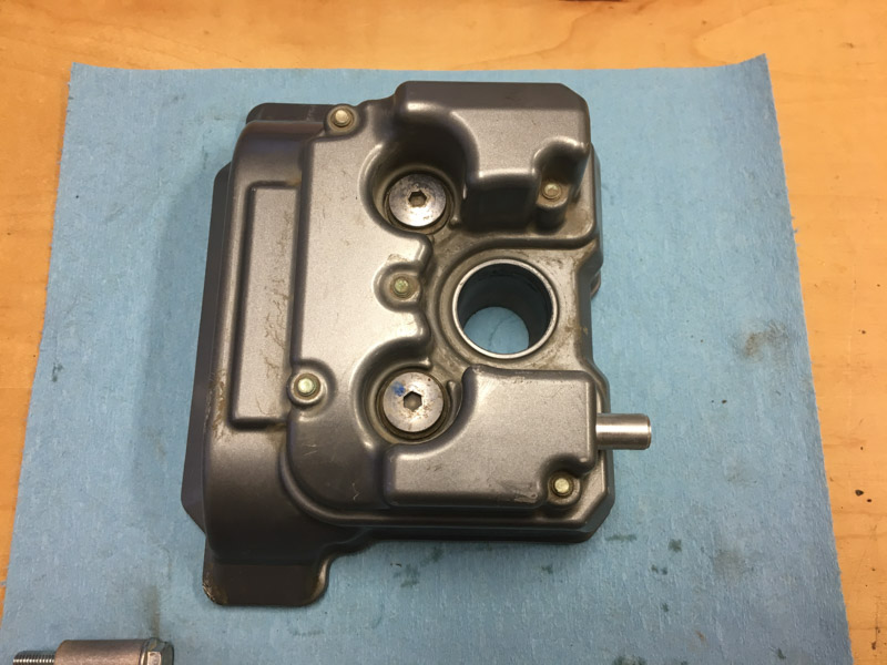
17. Unbolt the valve cover. You should be able to wiggle it up, right, forward, and then rotate it clockwise to get it out of the frame. Mounted on the throttle body is a little vacuum widget that looks like it will block the cover, but you actually do not need to remove this part and can wiggle the valve cover around it. In the picture below, I've already removed the valve cover, but the widget is the thing with two Phillips (actually JIS) screws and two hoses going into it.


Check valve clearance
Now the valves are exposed, and you can check clearances with feeler gauges. The clearance specs are:

Intake (rear of bike): 0.13-0.20 mm (0.0051 - 0.0079 in)
Exhaust (front of bike): 0.23-0.30 mm (0.0091 - 0.0118 in)

I was able to easily insert a 0.10 mm feeler under the intake cams, but a 0.15mm feeler was tight, indicating they were probably right on spec around 0.13 mm.

The exhaust cams were easy with a 0.20 mm feeler, but very tight with a 0.25 mm feeler. So, probably a bit too tight vs. spec, but that's how it came from the factory and 27,000 km later it's running fine, so I'm not going to change anything.          

Confirm your cam timing
18. With the crank at TDC (you can double-check TDC by looking in the spark plug hole and confirming the piston is up), check the timing of the cam shafts: the correct position is with the lobes facing away from each other, and the timing marks on the cam gears parallel with the top edge of the cylinder head. Note that it is surprisingly easy to skip the timing chain on the cam gears, so you definitely want to confirm the positions before reinstalling the valve cover.


19. If you need to adjust the cam timing, first loosely slip a wire under the timing chain and loop it over the frame to prevent the timing chain from dropping into the case. Then rotate the left (exhaust) camshaft into position first, then rotate the intake (right) camshaft. I used a dental pick to hold up the timing chain over the teeth, making it easy to rotate the cam gear.
20. Double check the position of the TDC mark down in the generator hole. At this point, everything should be perfectly aligned.

Reinstall the tensioner
21. First you need to compress the tensioner piston and lock it into place. You can do this by squeezing it between your thumb and fingers, with the piston end at your thumb, while rotating the body of the tensioner (the piston only retracts with a winding motion). Once the piston reaches the bottom, hold it there and gently squeeze the little wire clip at the end to lock it into the groove, and gently release your thumb pressure. The piston should stay in place. If this method proves too tricky, you can gently squeeze the piston in a non-marring vise. Note that applying slight pressure to the end of the piston releases the wire clip and allows the piston to extend--you'll need to do this after re-installing the tensioner.
22. Insert the tensioner into the engine case, using a new gasket if necessary (wasn't in my case) and install only the front mounting bolt, using a new crush washer. Snug the bolt just past finger-tight, but not so you crush the washer. Depending on how setting the tensioner goes in a moment (e.g. if you goof up and jump the timing chain), you may need to remove and reset the tensioner, so using just one bolt to hold it in place will avoid a lot of fiddly frustration.
23. Now you need to release the tensioner piston so it presses firmly against the chain guide and takes up the slack in the timing chain. The trick is to do it without skipping the chain: hold the left (exhaust) gam gear firmly with your left hand, and slowly turn the crankshaft counterclockwise while keeping hand-pressure on the chain. After about half a revolution of the crank, the chain should tighten up enough that you hear a slight "click" as the tensioner release the piston, and it'll be obvious to see the chain slack slowly disappear.
24. Carefully turn the crank by hand counter-clockwise over a few revolutions to confirm that the TDC mark and cam timing positions are correct, and chain tension is firm. In my case, after setting the tensioner I found that both of my cam gears were just slightly off horizontal by half a tooth, even though the TDC mark was in the right place. This appears to be within normal tolerances, as experimenting with moving the cams by a tooth either way to try to correct the angle only made it worse.
25. Install the second tensioner bolt and torque both bolts to 10 N-m.
26. Inspect the valve area for debris. If there's any grit, wipe it away carefully.
27. Reinstall the valve cover. The manual says to replace the valve cover gasket, but if it's clean and in good shape, you should be able to re-use it without issue. For extra security, I ran a thin bead of silicone gasket sealer (Hondabond HT) on the underside of the gasket before mounting it back on the head.

Reinstall all the other bits by following the instructions in reverse order.

It's a good idea to change the oil after this procedure, to flush out any grit that may have fallen into the valve area.
 
I'm happy to report that after reassembling my bike, it fired up perfectly the first time and purred like a kitten. The start had none of the jangly sound that set me on this service path, and the engine just sounds really good.


As a footnote, I disassembled the old (left) and new (right) tensioners to see if I could notice any differences.


Other than the date code and part numbers on the case, the parts seem identical, although the new tensioner is noticeably easier to compress the original one.