Showing posts with label jet engine. Show all posts

Sunday, December 15, 2013

Jet Engine - Part 7

This morning I painted and cured the exhaust scroll after grinding off a few spatters and bumps, and filing the flange flat. It turned out reasonably well considering how pitted the original part was.


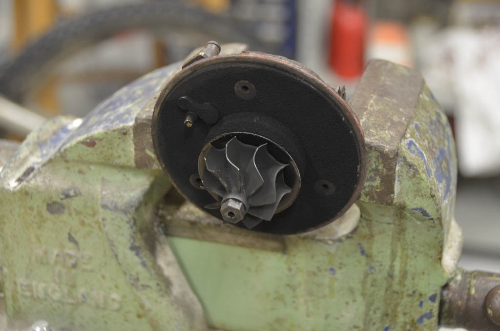
Then it was assembly time. There's really no secret to this: all the parts go together one way only, except for the shield under the turbine. At first I thought it should cup away from the base of the turbine, since that seemed to match the existing curve better. But after assembling the core I heard the shield rattling around. A quick Internet search showed it should be mounted the other way, curving towards the turbine. This made for a snug fit. The photo shows the correct orientation.


I should mention that it is a good idea to replace the retainer ring on the shaft under the turbine. Since the old one was a pain to remove it was tempting to avoid this step, but under was some coked oil that needed to be carefully scraped out with a dental pick. Cleaning up little details like this can make the different between having the seals last (because of lower friction and the ability for cooling oil to get in there), or blowing them out fast.

A few drops of oil on the shaft and it all slid together beautifully. There were two circle clips in the rebuild kit and I'm not entirely sure what they're for. One could be a replacement for the expansion ring at the bottom of the core, to prevent the brass journal bearing from falling out the bottom. Since there are two replacement journal bearings, it's probably a new clip for each. I just left the original clip in place since it seemed fine. It is unlikely to fail and would be really hard to remove anyway since it's a coil-style and not a circle-clip with ears for a tool.


Admittedly, the washers to hold on the turbine scroll look a little hokey. The originals are too corroded to reuse and are an unusually thick material. I'll have to look for some decent replacements. The seal on the turbine scroll is my main concern with this turbo. I'm not sure how gas-tight it'll be. It wouldn't be good for hot combustor gases to blow out around the perimeter.


The shaft spins nicely and nothing seems to be interfering, so I think things are good to go to the next step: designing and fabricating the combustor. Before I can start that, I need to finish my thermo calculations and come up with a design spec. There are some online tools to help locate the air holes for optimal flow of shield air and combustion air. However, some experimentation will be required before I'm confident to attach the combustor to the turbo.


As you can see, I've rotated the compressor outlet so it's pointing the same way as the turbine inlet. The combustor will mount to the flange I welded to the turbine inlet, and a U-shaped hose will connect the combustor inlet to the compressor. It's looking pretty industrial already and I need to start thinking about how to make this look steampunk with appropriate details for the overall assembly. Lots of brass and stained oak, I think.

Update (April 4, 2014): Work and the need for a MIG welder have delayed my progress. But I promise: more to come!

Saturday, December 14, 2013

Jet Engine - Part 6

Welded the flange this morning. Well, actually, Chris Branje (John Branje's son) stick-welded it for me. He earned a case of Bud for his mighty fine job. Check it out:


The procedure was to pre-heat the parts to 800F in the kiln, giving them a good soak before welding. Chris used a nickel flux rod for filler, laying down a remarkably nice fillet. Penetration looked good all around except deep in the scroll crevice where it was hard to reach. We decided to flip the scroll over and just fill that entire area with rod to ensure a gas-tight fit for the flange. The inside of the flange was perfectly aligned and no cleanup there is needed. 

Thanks to the preheating, Chris said the welding was like butter. He's successfully welded cast iron before, but this was the easiest he's seen yet. 

After welding he peened the welds lightly to knock off the dross and I stuck the whole shebang back into the kiln. After re-heating to 800F, I let it cool slowly to about 160F over 6 hours. No cracking observed in the finished product. Oxidation is mild and cleans up easily with a wire wheel on the Dremel. After a thorough cleaning, I'll paint it with the black VHT paint and fire it again in the kiln. 

After Chris finished he let me have a go welding some scrap steel. I had a hard time sparking it up and not getting the rod to stick, never mind dragging a puddle and actually welding. This was my first time trying stick welding. Gives me all the more respect for skilled welders! Hopefully I have better luck with a MIG. 


Thursday, December 5, 2013

Jet Engine - Part 5

Time to test that Very High Temperature paint. It's actually a ceramic material, although you need a microscope to read that detail on the label. Prep was pretty straightforward: thorough cleaning with degreaser and water to rinse out all the sandblasting dust, then quick shot of WD40 to displace the water, then another degrease with acetone and then a quick shot of compressed degreaser. The parts came out nice and clean after that, with no apparent oxidation even on the cast iron. You can see why it's called gray iron. Compare the appearance of these parts now with the rusted and filthy junk at the start!

Then it was time to mask and spray. I chose black for the hot turbine parts and red for the compressor. There's not much choice in this temperature range anyway, and these colors should look suitably Victorian. Two light coats and then one medium coat all done within the recommended one hour max, and then into the kiln for a three stage cure at 250, 400, and 600F with a 30 minute soak and cool down between each heat. That red sure looks bright right after painting.


I put the cast iron turbo core and the compressor cover plate under a kiln shelf so it wouldn't be exposed to direct heat from the elements and the little bit of crap that comes off the elements as they expand and contract. I was also curious to see how direct and indirect heating would affect the paint cure. The next morning showed an interesting contrast: the scroll cover which was under the shelf was a nice bright red (although not as bright before curing), whereas the scroll case left exposed to the direct heat was a dull red. Either the direct heat did what it should, or the indirect heat did what it should--but one of them isn't quite right. Thumbnail scratch tests of the three parts showed that the paint is more fragile than I anticipated. Oh well, we'll see what happens when it's really cooking. Hopefully it slows down the oxidation at least a little bit.


The turbo core also took on a blue sheen from surface oxidation due to prolonged heating. Not sure why it would've been so hot for so long: I double-checked my kiln program, but maybe my ramp-down rates were too low. Anyway, this oxidation is cosmetic and should have no impact on the turbo performance since the moving bits are supported by the bronze bearing and an oil film, and there's nothing left to flake off.

Next step was to rig a method of holding the flange to the turbine scroll for welding. I used a scrap of 1/4" plate for a base and then wired everything in place, engraving a groove around the scroll case where it contacts the flange so I can relocate it precisely in case something moves. John Branje, our local expert welder, will attempt to MIG these pieces together using a nickel filler and by peening the welds between passes. Before that I will pre-heat the parts to about 800F in the kiln so there's less risk of heat shock (which can crack the iron casting or weld), and then post-weld slowly cool the parts in the kiln for the same reason. As you can see from my set-up, it'll be easy to lift the parts out of the kiln and onto a ceramic fibre sheet using a long steel rod inserted through the scroll case. One of the benefits of working with kiln-formed glass is I have refractory materials just lying around!


If it all holds together, I'll clean up and paint the scroll case black as well.

The turbo rebuild kit arrived today. All the parts appear to be of high quality and fit perfectly. As a bonus, the replacement o-rings smell like cinnamon oil. Given the kit cost only $78 delivered from Amazon, I should've bought it long ago and just moved on with the project. It's exciting to see this crappy old turbo start to show some promise here! Fingers crossed that by the end of the weekend I can have it all back together and ready to plumb for oil pressure. Then the project really begins.


Saturday, November 30, 2013

Jet Engine - Part 4

Over the last few weeks I've done a pile of work on my jet engine project. It's been on the back burner (afterburner? haha!) for the last few months while I focused on riding, the Wilbur Mine project, and work--which pays for the fun stuff.

Unfortunately, most of the work I've been doing is math: calculating all the thermodynamic transfers from the compressor to combustor to turbine, so I could determine the design requirements for the combustor and develop a fuel injection system. This exercise proved to be quite challenging since it's been about 20 years since my last thermo class, and many important details for the parts I have and system I want to design had to be deduced from a pile of measurements, web info, and educated guesses. I'm not going to go into all the details here just now. For one thing, this blog lacks an equation editor; for another, it would be more useful if I proved out my assumptions before going to all the effort of showing my work.

For now I will say that I found an extremely useful paper from an MIT engineering student who went through the same design exercise as a 4th year project. However, that design used a different turbo than mine and adopted a propane fuel source. Since I want to use kerosene, I needed to recalculate the entire design starting from a different chemical (combustion) reaction, and using a different performance map for my turbo (a Garrett VNT-15 from a VW TDI). The operative concept is calculating the enthalpy of reactants and products through the three stages of compressor, combustor and turbine.

I've completed the calculations and come up with a preliminary design spec. The next step is to design the combustor itself, now that I know the required fuel flow, input and output temperatures, and mass air flow through for my desired operating point.

Meanwhile, I took a break from the math and got my hands dirty. Machining a new main shaft journal bearing has been a real nuisance. I successfully made most of the part to 0.0001" tolerance compared to the original, then took it to a machine shop to bore out the critical internal diameter which includes two steps (the bearing surface) and a recessed area to allow pressurized oil to reach the bearing surfaces. I was unable to make a boring tool fine enough to cut the inside to the required profile, and was reluctant to buy the required tool for about $250. Hence the machine shop. But they screwed up the diameter so now the whole part is junk. Even if I got the interior right (which I'm confident I could), there was the other problem of how to machine an offset circle in one end to accommodate the anti-rotation plug. That would've required a 9mm end mill plus a way to mount it and the part for machining. All told, I was looking at several hundred dollars of tooling.

The easy solution was to order a bearing rebuild kit, which I did for $78 from Amazon. This proved essential anyway, because when I dry-fitted the turbo with my junked new bearing, I discovered that one of the thrust bearings needs to be replaced as well. Plus there's a redesigned oil plate cover in the rebuild kit which is supposed to improve cooling. Bottom line is the kit should solve a bunch of problems and let me move on to more fun things. It arrives next week.

Today's job was sand-blasting all the cast components to remove rust and prep them for painting with Very High Temperature paint. This paint is good to about 2500F and will be applied to all the hot components to prevent further oxidation. The paint is really a ceramic material that sprays on and must be cured at high temperature. Fortunately I now have my glass kiln up and running, so I can cure the paint to 1700F if necessary, which is well above the anticipated ~1100F operating temperature I expect from the jet engine. As you can see, the clean cast iron looks quite different from the crusty lump I started with. This turbo is is in really poor condition--lots of surface corrosion which has eaten away substantial metal--but it should hold together OK. The important bits are there and it doesn't need to take further abuse from a car engine.


The next step was to fabricate a flange for turbine inlet to which I can attach the combustor. This is going to be a tricky operation and it may well fail: I need to weld the mild steel flange to the cast iron turbine housing. It is metallurgically possible to weld cast iron to steel using a nickel filler, but the challenge is keeping everything at the same temperature so the iron or weld don't crack. Cast iron contains a lot of carbon compared to mild steel, which makes it brittle. This problem is exacerbated by the grungy iron of the turbo, which has been soaking up even more carbon from the hot exhaust. The trick will be to heat everything to the same temperature in my kiln before MIG welding it, peening the weld periodically to remove stresses, then cooling the whole welded assembly slowly. This will be a task for John Branje, my local welding expert, who offered to perform the delicate operation for me in my shop.


The flange was cut from 1/4" plate using a combination of angle grinder, jigsaw, and drilling according to a template I made based on the inlet shape. Lots of filing later, it ended up looking pretty good. It'll be important to clean everything before welding, because any contaminants could reduce the ability to weld. I also bevelled the outer edge of the casting to 45 degrees to allow a bit more penetration for the weld bead. Not sure how easy it'll be to get a MIG in there.


Tomorrow I'm going to try painting the all the turbo housing components except for the turbine scroll, which I'll do after it's welded and cleaned up. Fingers crossed that I can pull this off! Otherwise I'm back to square one on this project, and will have to look for a different turbo design.


Wednesday, March 13, 2013

Jet engine project - Part 3


After spending several nights experimenting with some ghetto homemade tooling to bore out my replacement main journal bearing, I couldn't rig something that gave a smooth enough surface over the length of the bore. So reluctantly, I took it to a reputable machine shop to see if they could complete this step for me. Surprisingly, they fared no better despite three hours of trying. Worse, now the bore hole is about 0.001" larger than I'd like and a bit rough. Can't fix that! What a bummer, because I'd managed to machine the outside to within 0.0002" of the original part.

So much for "saving money"... now I'll just buy the tooling myself and have another go. That means making a new bearing from scratch. However, this time I'll start with the borehole and work to the outside. There's still the question of how to accurately mill the end cutout without a milling machine. I may be able to do that on my drill press--slowly. It's only brass, after all. None of this stuff would be a challenge on a CNC lathe but it's surprisingly tricky to do on a manual lathe. I've even tried maple jigs for offset turning the end mill. I could machine the maple to within a few ten thou of runout, but just could not get a decent interrupted cut in the brass with my makeshift tooling.


Tuesday, January 15, 2013

Jet engine project - Part 2


I hadn't really inspected the main journal bearing closely up to now, so when I finally did I was dismayed to discover that in fact it shouldn't be in two pieces. Funny what a little grimy oil can obscure!


That little ring on the right is supposed to be attached to the piece on the left. I thought maybe I'd snapped it off somehow when I took apart the seals, but closer inspection suggested that it probably torqued off last time the turbo operated. The brass in the portion of the journal inside the smaller piece was galled, probably from heat. I suspect the bearing lost oil pressure or maybe had a blockage at this end, and allowed the hot end of the bushing next to the exhaust turbine to overheat. Not a happy donor car at all. Hopefully there isn't a problem with the end seals around the thrust bearings. Visually they seem fine.

Close inspection of the shaft suggests it's still serviceable. I took a zillion measurements to get a sense of the dimensions and tolerances I'm dealing with. It's all metric apparently, but most of my tools are in inch so that's what I'm going to use, although some of the numbers seems weird. There's a good 0.001" of clearance to work with between the shaft and journal which would be filled with the pressurized oil that serves as the working bearing. The shaft still measures consistently within 0.0001-0.0002" along its bearing points, so any deviations above the surface won't penetrate the oil skin into the brass proper. Any microscopic grooves in the shaft bearings shouldn't have any impact on performance. They certainly pass the fingernail test. I will need to measure run-out as well, but I don't anticipate it being a problem. 

After searching the internet for a replacement journal bearing, all I could find were complete rebuild kits with parts I don't think I need (famous last words?). I can't afford to pay $120+ for this part. There's a proliferation of el-cheapo options from some guy named Rothenbacher who runs various internet parts stores which all seem to actually be the same business. However, online reviews suggest that parts quality is extremely poor and the businesses are awful to deal with. Two apparently reputable parts companies that I contacted never got back to me. 

That leaves me the the sole option of making my own journal. It's not a technically complicated part--it's just brass, after all--but it'll be vital to get the inside journal dimensions just right. 

So, I spent an entire evening making careful measurements and thinking about a strategy to make this piece. 


First off, my lathe wasn't up to snuff for these tolerances. It took an entire evening to tear it apart, polish the ways, and generally tune it up to eliminate unwanted play. It was due for some TLC anyway since I moved shops. Some test cuts in scrap brass showed I could consistently achieve cuts within a few ten thou, so I know I'm now in the ballpark. Yay Busy Bee. 

Second, I lacked some important tooling to work brass at this scale and achieve smooth finishes and the profiles I needed. To make tooling, I needed to use my grinder--and it's had a chronic wobble on the fine stone that I needed to use. So another evening was spent truing the grinding wheel and carefully carving out a cutter for fine surface work, and a roughing-out tool--both in HSS. Roughing out the journal with these tools showed they worked perfectly and well within the tolerances I sought. A few bucks of type 360 brass rod later, and I'm on my way to fabricating this critical part.


The hardest two cuts will be first the inside of the journal between the actual bearing surfaces (critical to allow just the right amount of bearing oil to pass through the journal), and then the milled-out dimple on the end which takes an insert to prevent the bearing from spinning inside the turbo. I don't have an inside cutter small enough for the former, and I'm nervous about rigging the finished bearing in a four-jaw chuck to cut the latter. Then I had the idea of making an inside cutter from an HSS drill bit, and modifying another HSS drill bit as an end mill. I'll experiment extensively with both tools as well as using the four-jaw chuck before committing to the procedure. 

I'm fairly confident I can make this part. Yes the tolerances are tight, but I the think film of pressurized oil will be somewhat forgiving within the tolerances I can achieve. As long as there's plenty of oil and enough freedom to prevent metal-on-metal contact, even my home-made journal should work fine. And I don't expect it will look any worse the the OEM one.  

Now it's off to make more tooling!  

Jet engine project - Part 1

If you're reading this blog, chances are it's because you're a gear head and so you may find this project interesting. In this case, the motor is the project and the wheels are optional.

I've always wanted a jet engine to play with. Nothing beats the scream of a turbine spooling up to 150,000 rpm and the oily smell of burning kerosene. Makes me think of travel and adventure.

Since I can't afford to buy a jet engine, my only option is to build one. This has been done before by many garage hobbyists and isn't really that complicated, but there are a few design challenges that will keep things interesting. 

If you look at an aircraft jet engine, it's basically a tube with a bunch of big internal fans inline with the central axis. Air enters the hole at the front of the tube and is compressed by the first few fans. Somewhere near the middle fuel is injected and ignited with the compressed air. The burning fuel expands rapidly and is forced to exit the rear end of the tube, first passing through more fans which are connected to and drive the front compressor fans. The hot air that is pushed rapidly out the back produces a lot of thrust. One of the most successful versions of a jet engine used in some older military aircraft had only seven moving parts in the main tube. Pretty simple concept for such impressive performance. 

One of the simplest jet engine concepts uses a car turbocharger for the compressor and gas turbine, with a combustor connecting the two components and a few support systems to provide oil pressure for the shaft bearing, ignition, and fuel control. A car turbo is designed for an almost identical purpose. However, instead of running on car engine exhaust, I'll be running on a stream of burning kerosene, pressurized into the exhaust turbine by the air compressor that normally would pump air into the car engine's cylinders. From a conceptual point of view the design is quite similar to an aircraft jet engine. However, in my version the air doesn't run in a straight line through all the fans; it has to follow a number of 90 degree bends to connect all the pieces. For that reason it's less efficient and doesn't generate much thrust, but if all goes well it'll sound and smell like its aviation kin. 

For my design I've started with a junked turbocharger from a Volkswagen diesel, probably a Jetta. My brother has a buddy who knew of one and since I could get it for free, the price was right on budget.


I forgot to grab a picture of the turbo when I got it, but it looks pretty much like the one above. It was in poor condition with lots of rust, seized fasteners, and extensive soot from what appears to have been damaged piston rings on one cylinder. It had been unceremoniously cut out of the engine bay with a torch and hammer. I wasn't sure it could be salvaged and the configuration and shape of parts was extremely inconvenient for a jet engine concept. It would need a lot of work. But it was free!

After two nights of vicious hacking and twisting with various tools, I'd managed to get most of the components apart. However, several key bolts and screws were seized into place with rust and no amount of loud swearing got them free. Eventually I had to drill them out, carefully avoiding damage to the iron casting itself which could not be repaired easily.


As you can see, the exhaust manifold is cast in one piece with the exhaust turbine. I wanted just one hole to which I could connect a combustor. That meant sawing off the manifold with a hacksaw. The leftover manifold will be good for practicing how to weld a steel flange to the turbo housing so I can attach the combustor. Welding to cast iron requires a few tricks but again, thanks to the Web I was able to find some excellent advice on what to do.


Meanwhile, on the fresh air side of the turbo, I had disassembled the compressor to inspect the oil bearing. You can see the little compressor wheel and the underside of the scroll casing it sits inside. I also had to drill out a screw because the stupid thing had seized even there, immersed in oil. The gold coloured parts are the oil bearing for the turbo shaft. Initially I was concerned about bearing play. Too much, and pressurized oil would leak out around the bearing and into the hot side being fed by the combustor. That would result in a lot of smoke and the rapid self-destruction of the whole turbo. However, after inspecting closely and comparing with examples on the web, it looks like I lucked out on the bearing. It should hold up for my purpose. 


Back on the hot side I faced a significant challenge: how to remove the scroll case cover from the scroll case so I could remove the exhaust turbine, inspect the bearing at this end and service some other components. As you can see from the assembly clamped in the vise (turbine shaft sticking straight up), the scroll case cover had seized into the case and no amount of whacking on it would break it free from its rust. I'd pretty much given up on gaining access and decided to try harsher methods: namely, a chisel. By putting the flat end of the chisel on the case and hammering on the point so I wouldn't accidentally damage the cast iron scroll case, I was finally able to crack the rust and tease off the cover. However, I forgot to wire the case to my vise and the damn thing flew sideways to the floor when it suddenly released. I quickly stuck out my foot to catch it before it hit the concrete floor and saved the case but whacked my leg with the heavy casting. Ouch.


 Now almost all the parts were free. The exhaust turbine was a sooty mess from the engine and the variable inlet vanes barely moved. More screws had to be drilled out to free these parts for cleaning.


Finally I had the whole thing apart and could see what I was dealing with. It looked pretty good under all the crud. Some epic filing on my hacksaw cut cleaned up the future flange point for the combustor. Other parts were rigged into the lathe to shave off rust. Much elbow-grease later I'd cleaned the worst of the corroded mating surfaces. Lots of debris remains to be thoroughly cleaned out before I can reassemble the delicate bearing, but I'm not going to do that until I can get the outside bead blasted to clean it of rust flakes and other crap. There's a high temp paint that will look good and should work up to 2000F. 


Today my son and I hit the fastener store in Ottawa for some replacement bolts and screws. Not everything matched exactly so I had to modify several fasteners on my lathe to get the right shapes and sizes. By the end of today I was able to dry-fit my modified components and re-orient the hot and cold scroll cases so they pointed in the same direction as needed to eventually position a combustor between them. Next step is the bead blasting and thorough cleaning in prep for reassembly. Then I can blank off the holes and work on a scheme to mount the turbo in a frame and get oil into and out of it. I've decided to aim for a "steampunk" look for the finished engine, sort of a cross between Victorian-era design and science fiction (check out this steampunk computer and motorbike). This gives some exciting possibilities for gauges and controls and I'll be hitting a nearby antique store to look for cheap old industrial junk I can modify to work. So far I haven't seen a steampunk jet engine.


Compared to what I started with a few days ago, this is looking rather promising!